Physics A Level | Chapter 23: Capacitance 23.7 Charge and discharge of capacitors
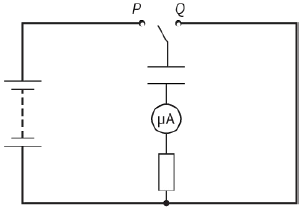
In Figure 23.18, the capacitor is charged by the battery when the switch is connected to terminal P. When first connected to P, a current is observed in the microammeter. The current starts off quite large and gradually decreases to zero. When connected to terminal Q, the capacitor discharges through the resistor and a current in the opposite direction is observed. As with the previous current, it starts off large and gradually falls to zero.
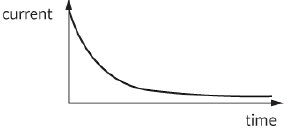
This shape of this graph it is quite common in sciences and it occurs in different situations – you will come across it again in radioactive decay in Chapter 29. In this case, it comes from the fact that, as charge flows off the capacitor, the potential difference reduces and so the current (the charge flowing per unit time) in the circuit also decreases. In radioactive decay, it occurs because as atoms decay, there are fewer atoms left to Charles’s law and, therefore, fewer decays per unit time.
This type of decay is called exponential decay and is described by the formula:
$x = {x_0}{e^{ - ky}}$
where x is the dependent variable, y is the independent variable, k and ${x_0}$ are constants and e is the exponential function (a naturally occurring number of value 2.7118 28 …).
Question
22) In the circuit in Figure 23.18, the resistance has a resistance of $2000\Omega $, the capacitor has a capacitance of $1000\,\mu F$ and the battery has an e.m.f. of $12 V$.
a: Calculate:
i- the potential difference across the capacitor when it is fully charged by the battery
ii- the charge stored by the capacitor when it is fully charged
iii- the current in the resistor when the switch is first connected to terminal Q.
b: Explain what happens to the amount of charge stored on the plates in the moments after the switch is first connected to terminal Q.
c: Based on your answer to part b, explain what effect this has on:
i- the potential difference across the capacitor
ii- the current in the resistor.
Once you have worked through Question 22, you should understand why the current gradually reduces: it reduces because of the current itself, as it takes charge off the plates.
What is the effect of changing the resistance in the circuit? There will be no change in the initial potential difference across the capacitor, but the initial current through the resistor will be changed. Increased resistance will mean decreased current, so charge flows off the capacitor plates more slowly and, therefore, the capacitor will take longer to discharge. Conversely, decreasing the resistance will cause the capacitor to discharge more quickly.
What is the effect of increasing the capacitance of the capacitor? The initial p.d. across the capacitor is, again, unchanged. So, with an unchanged resistance, the initial current will be unchanged. However, there will be more charge on the capacitor and so it will take longer to discharge.
From this, we can see that the time taken for a capacitor to discharge depends on both the capacitance and the resistance in the circuit. The quantity RC is called the time constant of the circuit. It is written using the Greek letter tau ($\tau $).
Question
23) Show that the unit of the time constant (RC) is the second.
The equation for the exponential decay of charge on a capacitor is:
$I = {I_0}\,\exp \,( - \frac{t}{{RC}})$
where I is the current, ${I_0}$ is the initial current, t is time and RC is the time constant.
The current at any time is directly proportional to the potential difference across the capacitor, which in turn is directly proportional to charge across the plate. The equation also describes the change in the potential difference and the charge on the capacitor.
So:
$V = {V_0}\,\exp ( - \frac{t}{{RC}})$
where V is the p.d, and V0 is the initial p.d.
And:
$Q = {Q_0}\,\exp ( - \frac{t}{{RC}})$
where Q is the charge and Q0 is the initial charge.
Question
24) A $400\,\mu F$ capacitor is charged using a $20 V$ battery. It is connected across the ends of a $600\,\Omega $ resistor with $20 V$ potential difference across its plates.
a: Calculate the charge stored on the capacitor.
b: Calculate the time constant for the discharging circuit.
c: Calculate the time it takes the charge on the capacitor to fall to $2.0 mC$.
d: State the potential difference across the plates when the charge has fallen to $2.0 mC$.
EXAM-STYLE QUESTIONS
1) A capacitor has a potential difference of $6.0 V$ across its plates and stores $9.0 mJ$ of energy.
Which row in the table gives the capacitance of the capacitor and the charge on its plates? [1]
| Capacitance / $\mu F$ | Charge / mC | |
| A | 500 | 3.0 |
| B | 500 | 18 |
| C | 3000 | 3.0 |
| D | 3000 | 18 |
2) A capacitor in an electronic circuit is designed to slowly discharge through an indicator lamp.
It is decided that the time taken for the capacitor to discharge needs to be increased. Four changes are suggested:
1- Connect a second capacitor in parallel with the original capacitor.
2- Connect a second capacitor in series with the original capacitor.
3- Connect a resistor in parallel with the lamp.
4- Connect a resistor in series with the lamp.
Which suggestions would lead to the discharge time being increased? [1]
A: 1 and 3 only
B: 1 and 4 only
C: 2 and 3 only
D: 2 and 4 only
3) A $470\,\mu F$ capacitor is connected across the terminals of a battery of e.m.f. $9 V$.
4) Calculate the charge on the plates of the capacitor. [1]
Calculate the p.d. across the terminals of a $2200\,\mu F$ capacitor when it has a charge of $0.033 C$ on its plates. [1]
5) Calculate the capacitance of a capacitor if it stores a charge of $2.0 C$ when there is a potential difference of $5000 V$ across its plates. [1]
6) Calculate the energy stored when a $470\,\mu F$ capacitor has a potential difference of $12 V$ across its plates. [1]
7) Calculate the energy stored on a capacitor if it stores $1.5 mC$ of charge when there is a potential difference of $50 V$ across it. [1]
8) A $5000\,\mu F$ capacitor has a p.d. of $24 V$ across its plates.
a: Calculate the energy stored on the capacitor. [1]
b: The capacitor is briefly connected across a bulb and half the charge flows off the capacitor. Calculate the energy dissipated in the lamp. [3]
[Total: 4]
9) A $4700\,\mu F$ capacitor has a p.d. of $12 V$ across its terminals. It is connected to a resistor and the charge leaks away through the resistor in $2.5 s$.
a: Calculate the energy stored on the capacitor. [1]
b: Calculate the charge stored on the capacitor. [1]
c: Estimate the average current through the resistor. [1]
d: Estimate the resistance of the resistor. [2]
e: Suggest why the last two quantities can only be estimates. [1]
[Total: 6]
10) An electronics engineer is designing a circuit in which a capacitor of capacitance of $4700\,\mu F$ is to be connected across a potential difference of $9.0 V$. He has four $4700\,\mu F$, $6 V$ capacitors available. Draw a diagram to show how the four capacitors could be used for this purpose. [1]
11) Calculate the different capacitances that can be made from three $100\,\mu F$ capacitors. For each value, draw the network that is used. [4]
12) This diagram shows three capacitors connected in series with a cell of e.m.f. $1.5 V$.
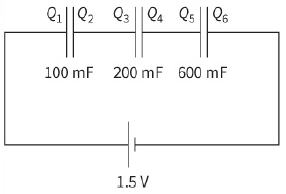
a: Calculate the charges ${Q_1}$ to ${Q_6}$ on each of the plates. [5]
b: Calculate the p.d. across each capacitor. [3]
[Total: 8]
13) a: State one use of a capacitor in a simple electric circuit. [1]
b: This is a circuit used to investigate the discharge of a capacitor, and a graph showing the change in current with time when the capacitor is discharged.
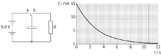
i- Deduce the resistance R of the resistor. [2]
ii- Explain why the current decreases as the capacitor discharges. [2]
iii- The charge on the capacitor is equal to the area under the graph.
Estimate the charge on the capacitor when the potential difference across it is $9.0 V$. [2]
iv- Calculate the capacitance of the capacitor. [2]
[Total: 9]
14) The spherical dome on a Van de Graaff generator has a diameter of $40 cm$ and the potential at its surface is $5.4 kV$.
a: i- Calculate the charge on the dome. [2]
ii- Calculate the capacitance of the dome. [2]
An earthed metal plate is moved slowly towards the sphere but does not touch it. The sphere discharges through the air to the plate. This graph shows how the potential at the surface of the sphere changes during the discharge.
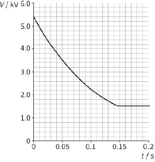
b: Calculate the energy that is dissipated during the discharge. [5]
c: Suggest why the discharge ceases while there is still some charge on the dome. [2]
[Total: 11]
15) a: Show that the capacitance C of an isolated conducting sphere of radius r is given by the formula:
$C = 4\pi {\varepsilon _0}r$ [2]
This diagram shows two identical conducting brass spheres of radius $10 Cm$ mounted on insulating stands. Sphere A has a charge of $ + 5.0 \times {10^{ - 8}}\,C$ and sphere B is uncharged.
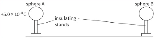
b: i- Calculate the potential at the surface of sphere A. [2]
ii- Calculate the energy stored on sphere A. [2]
Sphere B is brought up to sphere A and is touched to it so that the charge is shared between the two spheres, before being taken back to its original position.
c: i- Calculate the energy stored on each sphere. [3]
ii- Suggest why there is a change in the total energy of the system. [1]
[Total: 10]
16) a: Define the term capacitance of a capacitor. [2]
b: This is a circuit that can be used to measure the capacitance of a capacitor.
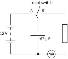
The reed switch vibrates back and forth at a frequency of $50 Hz$. Each time it makes contact with A, the capacitor is charged by the battery so that there is a p.d. of $12 V$ across it. Each time it makes contact with B, it is fully discharged through the resistor.
i- Calculate the charge that is stored on the capacitor when there is a p.d. of $12 V$ across it. [2]
ii- Calculate the average current in the resistor. [2]
iii- Calculate the average power dissipated in the resistor. [3]
c: A second capacitor of the same value is connected in series with the first capacitor.
Discuss the effect on both the current recorded and the power dissipated in the resistor. [4]
[Total: 13]
17) a: Explain what is meant by the time constant of a circuit containing capacitance and resistance. [2]
b: A circuit contains capacitors of capacitance $500\,\mu F$ and $2000\,\mu F$ in series with each other and in series with a resistance of $2.5\,k\Omega $.
i- Calculate the effective capacitance of the capacitors in series. [2]
ii- Calculate the charge on the capacitor plates when there is a potential difference of $50 V$ across the plates. [2]
iii- Calculate the time taken for the charge on the plates to fall to $5\% $ of the charge when there was a p.d. of $50 V$ across the plates. [2]
[Total: 8]
SELF-EVALUATION CHECKLIST
After studying the chapter, complete a table like this:
| Ready to move on | Almost there | Needs more work | See topic… | I can |
| 23.1 | define capacitance of both capacitors and spherical conductors | |||
| 23.1 |
recall and use the formula: $C = \frac{Q}{V}$ |
|||
| 23.1 | recognise that the unit of capacitance is the farad (F) | |||
| 23.3 |
derive and use the formula: ${C_{total}} = {C_1} + {C_2} + {C_3} + ...$ for capacitors in parallel |
|||
| 23.7 |
recognise that the time constant for circuits containing capacitance and resistance is: $\tau = CR$ |
|||
| 23.4 | derive and use the formula: $\frac{1}{{{C_{total}}}} = \frac{1}{{{C_1}}} + \frac{1}{{{C_2}}} + \frac{1}{{{C_3}}} + ...$ for capacitors in series |
|||
| 23.2 | determine the energy stored in a capacitor from the potential–charge graph | |||
| 23.2 | recall and use the formulae: | |||
| 23.7 | understand that the decay of charge on a capacitor, the discharge current and the potential difference across the plates are exponential decays | |||
| 23.7 | recognise and understand that the rate of discharge is dependent on the time constant of the circuit | |||
| 23.7 |
recall and use the equation: $x = {x_0}\,\exp ( - \frac{t}{{RC}})$ for potential difference, discharge current and charge on the plat |